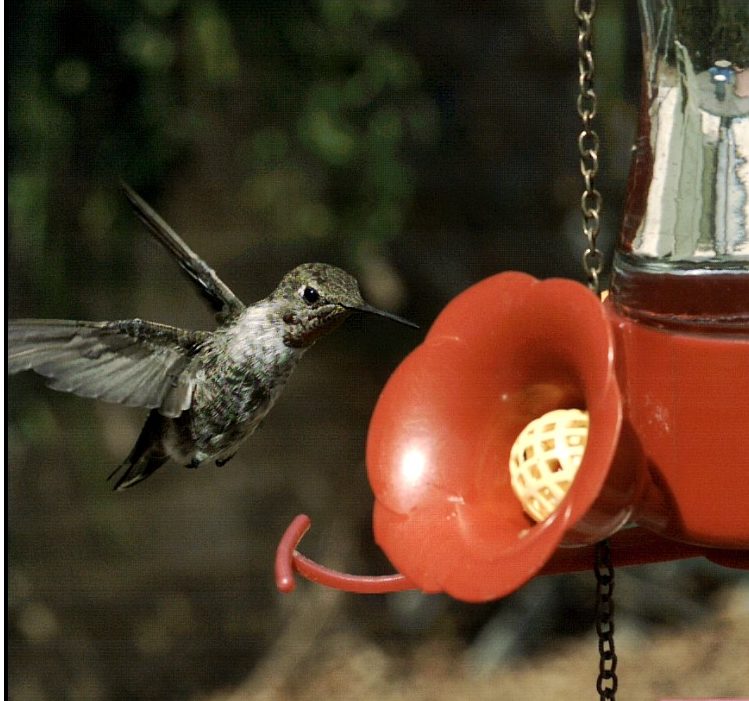
Hummingbird bit-selection video
In Part 1, we introduced a few concepts:
- A “bit” is a binary digit
- Mono images with higher bit depths have more shades of gray
- Color images with higher bit depths have more possible colors
- Most displays are only capable of presenting 256 shades of gray or 256 shades each of red, green, and blue, which yields over 16 million colors
In Part 2 we will cover:
- Bit Selection for TS, IL, and HS cameras
- Bit shifting
- Bit shifting vs Dynamic Range
- Bit shifting vs Noise
Some Fastec cameras have 10-bit sensors, and some have 12:
| Camera | Number of bits |
| IL3 | 10 |
| IL5 | 12 |
| TS3 | 10 |
| TS5 | 12 |
| HS5 | 10 |
| HS7 | 12 |
Bit selection for 10-bit cameras:
Understanding bit selection is challenging. We will be using bar graphs, lookup tables, and x/y graphs (refered to as curves) to help illustrate the working of bit selection. As all of these tools are used to express the same information, focus on whichever of these makes sense to you.
Dynamic Range, DNR
As a camera is exposed to more and more light, it responds by increasing the pixel values of its images. At saturation, the pixel values will cease to increase. Decreasing the quantity of light has the opposite effect, reducing the pixel values. And, at some point, reducing the amount of light no longer has an effect.
The camera’s Dynamic Range, is the range from the smallest amount of light the camera will respond to, which we set to Black, to the largest amount of light the camera will respond to, which we set to White. The DNR of a camera, is thus the amplitude ratio between the smallest and greatest quantities of light the camera can discern.
The ratio is expressed in dB, which for these purposes is defined as root power ratio of 101/20 (or, for every 20 dB you see a 10-fold increase). So @ 20dB the ratio is 1:10; @ 40dB the ratio is 1:100; and @ 60dB the ratio is 1:1000.
Most high-speed sensors operating in standard modes have DNRs of somewhere between about 54dB and 60dB, One may expect (albeit without certainty) that the smallest discernable change in amplitude of light for the sensor may be on the order of 1:1000, which correlates well with 10-bit data (1024 pixel values). High-speed sensors typically output 10 to 12 bits.
Image data viewable on PC displays however is limited to 8-bits per pixel in mono (256 shades of grey), or 8-bits for each RGB channel or about 16.8 million colors. Typically the 8 bits of image data from the high-speed sensor will be selected before processing, or 10- or 12-bit image data will be converted to 8-bit data via lookup tables (LUT) or some other image processing.
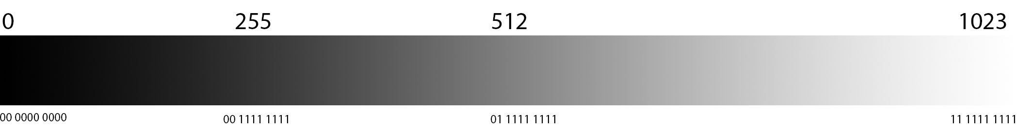
Selecting 10 Bits:
Full dynamic range of sensor with a range of 1024 pixel values, from 0 to 1023: 0=black; 1023=white
All bits are saved to camera memory during recording.
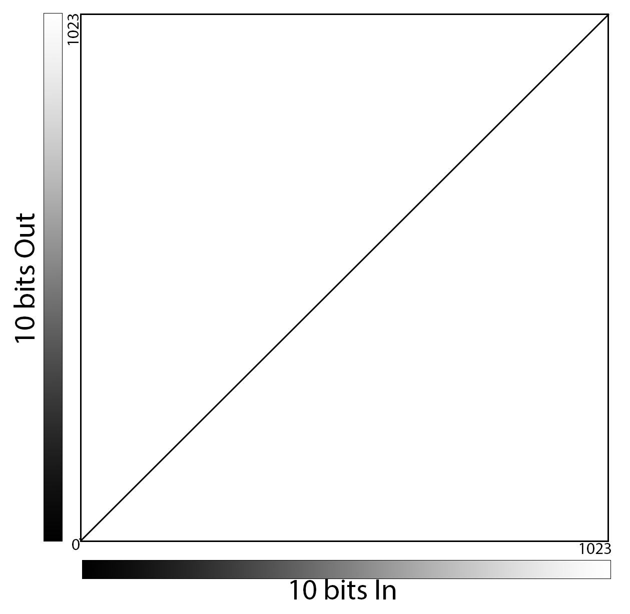
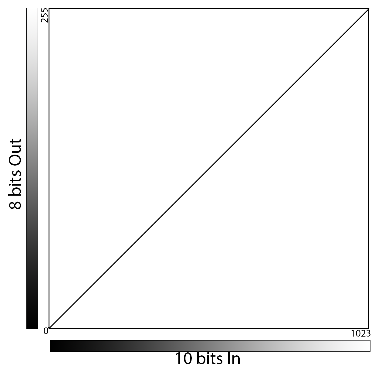
Here we have plotted the linear 10-bit curve on x/y axes in the manner of a familiar “curves” function seen in popular image processing applications, including Fastec’s FasMotion. The X axis represents input values while the Y axis represents Output values. The slope of the curve suggests the gain, which in this case is 1:
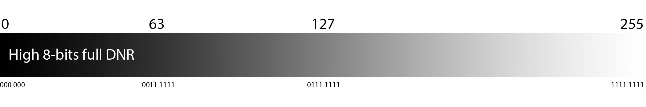
Selecting High 8 bits:
Think of it as stretching 8 bits over the full dynamic range of sensor with a range of 256 pixel values, from 0 to 255. The sensor produces all 10 bits, but only the upper 8 are saved to memory. The two least significant bits are lopped off.
Here is a portion of a 10- to 8-bit LUT. With the high 8-bits selected, the 256 output values are spread evenly across gamut of 10-bit values.
| 10-bit values | (dec) | 8-bit values | (dec) |
| 00 0000 0000 | 0 | 0000 0000 | 0 |
| 00 0000 0001 | 1 | 0000 0000 | 0 |
| 00 0000 0010 | 2 | 0000 0000 | 0 |
| 00 0000 0011 | 3 | 0000 0000 | 0 |
| 00 0000 0100 | 4 | 0000 0001 | 1 |
| 00 0000 0101 | 5 | 0000 0001 | 1 |
| 00 0000 0110 | 6 | 0000 0001 | 1 |
| 00 0000 0111 | 7 | 0000 0001 | 1 |
| 00 0000 1000 | 8 | 0000 0010 | 2 |
| 00 0000 1001 | 9 | 0000 0010 | 2 |
| 00 0000 1010 | 10 | 0000 0010 | 2 |
| 00 0000 1011 | 11 | 0000 0010 | 2 |
| 00 0000 1100 | 12 | 0000 0011 | 3 |
| 00 0000 1101 | 13 | 0000 0011 | 3 |
| 00 0000 1110 | 14 | 0000 0011 | 3 |
| 00 0000 1111 | 15 | 0000 0011 | 3 |
| 00 0001 0000 | 16 | 0000 0100 | 4 |
…continuing
| 10-bit values | (dec) | 8-bit values | (dec) |
| 00 1111 1101 | 253 | 0011 1111 | 63 |
| 00 1111 1110 | 254 | 0011 1111 | 63 |
| 00 1111 1111 | 255 | 0011 1111 | 63 |
| 01 0000 0000 | 256 | 0100 0000 | 64 |
… continuing
| 10-bit values | (dec) | 8-bit values | (dec) |
| 01 1111 1101 | 509 | 0111 1111 | 127 |
| 01 1111 1110 | 510 | 0111 1111 | 127 |
| 01 1111 1111 | 511 | 0111 1111 | 127 |
| 10 0000 0000 | 512 | 0100 0000 | 128 |
…continuing
| 10-bit values | (dec) | 8-bit values | (dec) |
| 11 1111 1101 | 1021 | 1111 1111 | 255 |
| 11 1111 1110 | 1022 | 1111 1111 | 255 |
| 11 1111 1111 | 1023 | 1111 1111 | 255 |
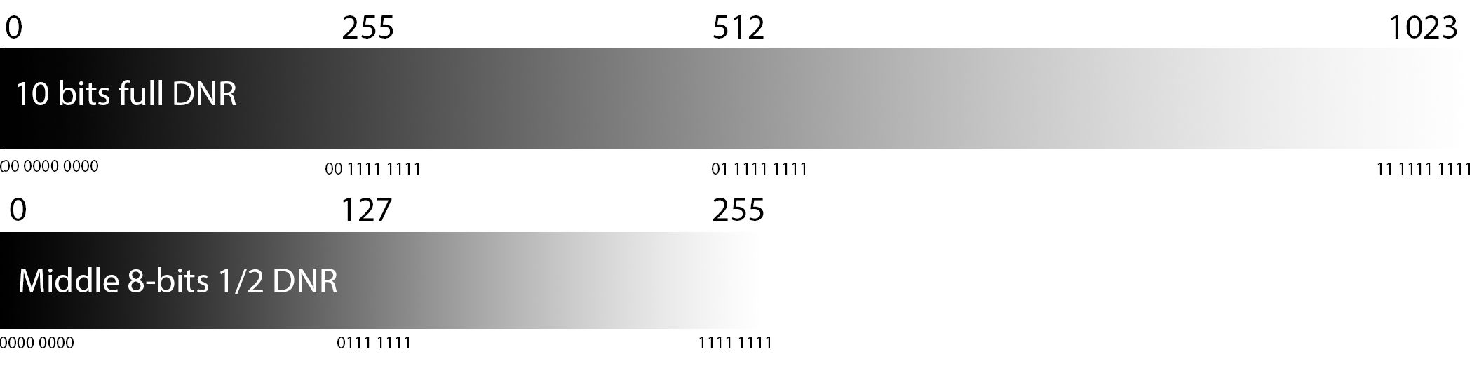
The gradients, below, demonstrate how selecting the high 8 bits stretch the full dynamic range over 256 pixel values:
When we express this in you x/y “curves” we see the same slope of 1 as before. The 256 values are stretched across the output side of this.
Bit shifting to Middle 8 bits
Using the middle 8-bits of a 10-bit image requires eliminating the most-significant and least-significant bits. This is the equivalent of 2x digital gain as only half the dynamic range of the camera is used as the output reaches is maximum value at the midpoint of the input. Images appear 2x as bright. Midrange values move toward saturation. Shadow areas become more visible. Noise level of the image is also 2x as great. All 10-bit values above 511 (01 1111 1111) will saturate.
| 10-bit values | (dec) | 8-bit values | (dec) |
| 00 0000 0000 | 0 | 0000 0000 | 0 |
| 00 0000 0001 | 1 | 0000 0000 | 0 |
| 00 0000 0010 | 2 | 0000 0001 | 1 |
| 00 0000 0011 | 3 | 0000 0001 | 1 |
| 00 0000 0100 | 4 | 0000 0010 | 2 |
| 00 0000 0101 | 5 | 0000 0010 | 2 |
| 00 0000 0110 | 6 | 0000 0011 | 3 |
| 00 0000 0111 | 7 | 0000 0011 | 3 |
| 00 0000 1000 | 8 | 0000 0100 | 4 |
| 00 0000 1001 | 9 | 0000 0100 | 4 |
| 00 0000 1010 | 10 | 0000 0101 | 5 |
| 00 0000 1011 | 11 | 0000 0101 | 5 |
| 00 0000 1100 | 12 | 0000 0110 | 6 |
| 00 0000 1101 | 13 | 0000 0110 | 6 |
| 00 0000 1110 | 14 | 0000 0111 | 7 |
| 00 0000 1111 | 15 | 0000 0111 | 7 |
| 00 0001 0000 | 16 | 0000 100 | 8 |
…continuing
| 10-bit values | (dec) | 8-bit values | (dec) |
| 00 1111 1101 | 253 | 0111 1110 | 126 |
| 00 1111 1110 | 254 | 0111 1111 | 127 |
| 00 1111 1111 | 255 | 0111 1111 | 127 |
| 01 0000 0000 | 256 | 1000 0000 | 128 |
… continuing
| 10-bit values | (dec) | 8-bit values | (dec) |
| 01 1111 1101 | 509 | 1111 1110 | 254 |
| 01 1111 1110 | 510 | 1111 1111 | 255 |
| 01 1111 1111 | 511 | 1111 1111 | 255 |
| 10 0000 0000 | 512 | 1111 1111 | 255 |
…continuing
| 10-bit values | (dec) | 8-bit values | (dec) |
| 11 1111 1101 | 1021 | 1111 1111 | 255 |
| 11 1111 1110 | 1022 | 1111 1111 | 255 |
| 11 1111 1111 | 1023 | 1111 1111 | 255 |
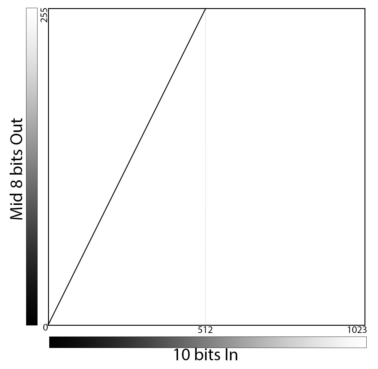
When we express this in “curves” we see a slope of 2. We also assume 2x noise.
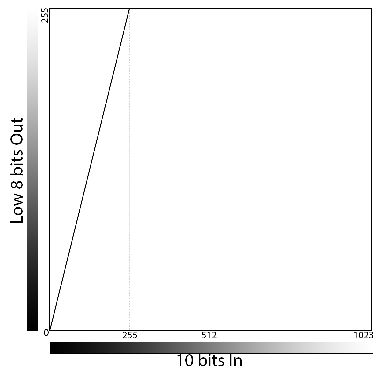
Bit shifting to Low 8 bits
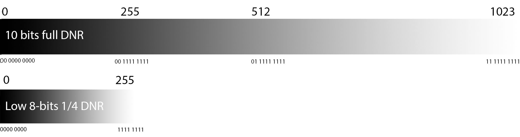
Using the low 8-bits of a 10-bit image requires eliminating the two most-significant bits. This is the equivalent of 4x digital gain as only one quarter the dynamic range of the camera is used. Images appear 4x as bright. Noise level of the image is also 4x as great. All 10-bit values above 255 (00 1111 1111) will saturate.
| 10-bit values | (dec) | 8-bit values | (dec) |
| 00 0000 0000 | 0 | 0000 0000 | 0 |
| 00 0000 0001 | 1 | 0000 0001 | 1 |
| 00 0000 0010 | 2 | 0000 0010 | 2 |
| 00 0000 0011 | 3 | 0000 0011 | 3 |
| 00 0000 0100 | 4 | 0000 0100 | 4 |
| 00 0000 0101 | 5 | 0000 0101 | 5 |
| 00 0000 0110 | 6 | 0000 0110 | 6 |
| 00 0000 0111 | 7 | 0000 0111 | 7 |
| 00 0000 1000 | 8 | 0000 1000 | 8 |
| 00 0000 1001 | 9 | 0000 1001 | 9 |
| 00 0000 1010 | 10 | 0000 1010 | 10 |
| 00 0000 1011 | 11 | 0000 1011 | 11 |
| 00 0000 1100 | 12 | 0000 1100 | 12 |
| 00 0000 1101 | 13 | 0000 1101 | 13 |
| 00 0000 1110 | 14 | 0000 1110 | 14 |
| 00 0000 1111 | 15 | 0000 1111 | 15 |
| 00 0001 0000 | 16 | 0001 0000 | 16 |
…continuing
| 10-bit values | (dec) | 8-bit values | (dec) |
| 00 1111 1101 | 253 | 1111 1101 | 253 |
| 00 1111 1110 | 254 | 1111 1110 | 254 |
| 00 1111 1111 | 255 | 1111 1111 | 255 |
| 01 0000 0000 | 256 | 1111 1111 | 255 |
… continuing
| 10-bit values | (dec) | 8-bit values | (dec) |
| 01 1111 1101 | 509 | 1111 1111 | 255 |
| 01 1111 1110 | 510 | 1111 1111 | 255 |
| 01 1111 1111 | 511 | 1111 1111 | 255 |
| 10 0000 0000 | 512 | 1111 1111 | 255 |
…continuing
| 10-bit values | (dec) | 8-bit values | (dec) |
| 11 1111 1101 | 1021 | 1111 1111 | 255 |
| 11 1111 1110 | 1022 | 1111 1111 | 255 |
| 11 1111 1111 | 1023 | 1111 1111 | 255 |
When we express this in “curves” we see a slope of 4. We also assume 4x noise.
What was the curve used in the video?
We will be exploring more of the “how to” aspect of bit depth in Part 3 of this series, but here is a little preview in the form of the LUT used in the introduction video. You can see that the slope of the curve is initially somewhere between that of the low- and mid- 8-bits (somewhere between 2 and 4), but that there is a flattening out of the curve at about the midpoint of the output. A very similar curve would be created by selecting a gamma of about 2 and a little contrast.

Quick Review
Here is a little table that summarizes all we have covered:
For a 10-bit camera:
| Bits Saved | Grey Levels | DNR | Gain | Noise |
| 10 | 1024 | 100% | 1x | 1x |
| 8-high (default) | 256 | 100% | 1x | 1x |
| 8-mid | 256 | 50% | 2x | 2x |
| 8-low | 256 | 25% | 4x | 4x |
What about the 12-bit cameras?
All of the concepts we have covered for 10-bit cameras carry through to 12-bit cameras. The only difference is that there are more choices:
| Bits Saved | Gray Levels | DNR | Gain | Noise |
| 12 | 4096 | 100% | 1x | 1x |
| 10-high | 1024 | 100% | 1x | 1x |
| 8-high (default) | 256 | 100% | 1x | 1x |
| 10-mid | 1024 | 50% | 2x | 2x |
| 8-11th bit high | 256 | 50% | 2x | 2x |
| 10-low | 1024 | 25% | 4x | 4x |
| 8-10th bit high | 256 | 25% | 4x | 4x |
| 8-9th bit high | 256 | 12.50% | 8x | 8x |
| 8-8th bit high | 256 | 6.25% | 16x | 16x |